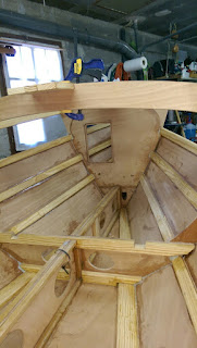
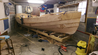
What makes a nice piece stand out ? The answer is probably entirely subjective but I sure have enjoyed building and manipulating this little component for the boat.
It will live its life as the mizzen mast step. It'll be buried down into the aft locker, covered in paint and not to be seen again. I've built it out of pieces of mahogany offcuts. I sure like the geometry and the nice grain of the wood.
I thought of dedicating a post to it as ... it won't be seen again after it is integrated to the boat. That makes it in a sense pretty ephemeral.
Monday, 30 November 2015
Monday, 23 November 2015
Inspiration
This photo from my internet friend Steve Earley keeps my motivation going through the current stages of the build.
With a self imposed deadline for my project set for the end of April 2016 in order to participate to the sail raid organised in the Venice lagoon, Steve's source of inspiration is indeed very helpful...
Wednesday, 11 November 2015
Some progress!
In the past few weeks some progress has been achieved. Different components have been spiled and dry fitted including the bench tops, the foredeck and its teak cover and the teak cockipt floor.
Also the inboard compartment has been fitted with a propeller inspection well (just about visible in the first photo above). This will allow to access the "saildrive" propeller from inside the boat in order to clean up fouling or to remove it altogether when racing. For this purpose I have designed a quick release mechanism allowing easily unplug the propeller with one hand through the well thus reducing drag when racing. Not that I will do a lot of that (or any at all) but I just thought it was an interesting feature to develop and integrate to the boat.
Of course none of this progress would have been possible without a helping hand or two ...
Also the inboard compartment has been fitted with a propeller inspection well (just about visible in the first photo above). This will allow to access the "saildrive" propeller from inside the boat in order to clean up fouling or to remove it altogether when racing. For this purpose I have designed a quick release mechanism allowing easily unplug the propeller with one hand through the well thus reducing drag when racing. Not that I will do a lot of that (or any at all) but I just thought it was an interesting feature to develop and integrate to the boat.
Of course none of this progress would have been possible without a helping hand or two ...
Saturday, 10 October 2015
A friend with teak is a friend indeed
A friend has proposed to me a bunch of teak strips (to use his words) he had laying around at his workshop since a while.
It turns out the bunch of strips are actually two half decks off a Riva like runabout project that was never finished.
They measure roughly 1.7 x 4 m, and consist of teak and elm strips glued to a sheet of marine ply. The whole professionally assembled and brand new. The whole lot offered to me pretty cheap. Thank you Vassilis, it'll be great help for my boat project.
I'm trying to step up the gears as the countdown to next year's VeLa raid in Venice has started and I have committed myself to participate with the Pathfinder. Sure, the paint will be still sticky the day we get there in mid May 2016.
The teak decks I have got from Vassilis will be used to line the cockpit floor and the forward bunkflat.
It turns out the bunch of strips are actually two half decks off a Riva like runabout project that was never finished.
They measure roughly 1.7 x 4 m, and consist of teak and elm strips glued to a sheet of marine ply. The whole professionally assembled and brand new. The whole lot offered to me pretty cheap. Thank you Vassilis, it'll be great help for my boat project.
I'm trying to step up the gears as the countdown to next year's VeLa raid in Venice has started and I have committed myself to participate with the Pathfinder. Sure, the paint will be still sticky the day we get there in mid May 2016.
The teak decks I have got from Vassilis will be used to line the cockpit floor and the forward bunkflat.
Tuesday, 6 October 2015
One mobile phone down .... work carries on
Despite the loss of my mobile phone containing several pictures of the ongoing progress of my Pathfinder build, work has carried on.
Photographic evidence of spiling and fitting the benches is lost however here's some photos of the latest developments:
- the forward deck beams are epoxied and screwed in place
- and here's a picture of the (to use a Formula 1 expression) power unit of the boat.
Instead of a standard transom hung outboard (which is unsightly to me on this kind of boat) or an outboard in a well, I opted for an own made inboard solution. The donor motor is a 1975 evinrude 4hp two stroke outboard. It is coupled to a honda 5 hp outboard gearbox and case through a belt and pulley arrangement.
The idea is to reproduce the concept of a sail drive, where the former honda gearcase will be built into the boats keel. A brass impeller pump is driven by gears from the gearbox shaft.
All components and parts were sourced rather cheaply on ebay while the motor itself was found in the trash bin of a small boatyard.
First power up of the modified engine in the boat worked really well. The adaptation work involved building an adapter flange, adding a shaft and bearings, belt and pulleys and an exhaust manifold. The engine itself received quite a lot of attention as well: new head gasket, coil, breakers and condenser and rebuilt carburettor. I have adapted the flywheel and recoil started from another similar aged evinrude outboard I order to keep the motor's height within the height of the main benches. The motor will be fully enclosed a watertight aft compartment not exceeding the height of the cockpit seats.
Being a small twin cylinder the motor is really quiet. It starts like a charm after I've adjusted the timing accurately.
Photographic evidence of spiling and fitting the benches is lost however here's some photos of the latest developments:
- the forward deck beams are epoxied and screwed in place
- and here's a picture of the (to use a Formula 1 expression) power unit of the boat.
Instead of a standard transom hung outboard (which is unsightly to me on this kind of boat) or an outboard in a well, I opted for an own made inboard solution. The donor motor is a 1975 evinrude 4hp two stroke outboard. It is coupled to a honda 5 hp outboard gearbox and case through a belt and pulley arrangement.
The idea is to reproduce the concept of a sail drive, where the former honda gearcase will be built into the boats keel. A brass impeller pump is driven by gears from the gearbox shaft.
All components and parts were sourced rather cheaply on ebay while the motor itself was found in the trash bin of a small boatyard.
First power up of the modified engine in the boat worked really well. The adaptation work involved building an adapter flange, adding a shaft and bearings, belt and pulleys and an exhaust manifold. The engine itself received quite a lot of attention as well: new head gasket, coil, breakers and condenser and rebuilt carburettor. I have adapted the flywheel and recoil started from another similar aged evinrude outboard I order to keep the motor's height within the height of the main benches. The motor will be fully enclosed a watertight aft compartment not exceeding the height of the cockpit seats.
Being a small twin cylinder the motor is really quiet. It starts like a charm after I've adjusted the timing accurately.
Thursday, 13 August 2015
Planking week!
An unexpected situation at work meant that the technical sea trials I should have attended for testing an underwater vehicle have been postponed. The holiday planning having been finalised beforehand this offered the unique opportunity of taking some prolonged time off at home. This would have been a first time experience of spending a week off at home as we always travel through Europe to see the family at every holiday break.
I decided therefore to declare an "all in" on the boatbuilding project and with the planks for my pathfinder already been CNC cut since day 2 of the project and looming at me from the shelves beside the boat, "Planking week" was given a clear for take off signal.
The planks are already cut to measure and take into account the required width of the clinker overlap. No spiling off the boat frame required. Given the size of the original ply sheet they are composed of three lengths, two roughly equal ones of around 2.2m and a third much shorter one. The joint is made with puzzle joints so no need for cutting scarfs. Easy!
Planking the whole boat took exactly 6 days, lots of epoxy and great lengths of time staring at the growing hull in the evening after cleaning up. It was nice to see the pile of planking material getting thinner by the day as for the first time in this project I was given the ultimate luxury of time to work on it.
The planks went on very well, matching the shape of the boat traced in 3D by the frames and the stringers exactly as it was on the 3D CAD model the templates were generated from. The only surprise were some long thin gaps appearing between the plank and the stringers towards the fore end of the boat. I initially thought that there was a problem with the bevels I had planed in the stringers and in the adjacent plank. I then realised that what I was seeing was perfectly normal as the relative angle between the planks becomes almost flat towards the bow of the boat and despite the bevel the thickness of the plank below the one being added makes the latter "come off" the stringer. I have filled the gaps with thin battens and thickened epoxy.
Sunday, 14 June 2015
A milestone
Plank #1 (starboard garboard) is fitted and glued! This is an important milestone in my poject as it proves that the plank shape that I had pre-cut by CNC waterjetting using 2D templates derived from the 3D model of the hull is actually spot on!
I had pre-validated the plank shapes through a 1:8 scale model, however all through the building of the boat's frame I was wondering whether it would really work as well in 1:1 scale: the boat's length is such that a small error could lead to trouble.
In the "traditional" building method proposed by the designer, the planks are spiled from the boat's skeleton composed of the floor, the frames and stringers erected over a strongback. In my case the planks are cut even before any part of that skeleton even exists. The risk therefore is that small inaccuracies in setting up the boat's strongback, frames and stringers would bring to disaster when fitting 5.8m long planks; and would the 3D unrolling of the boat model to yield the 2D templates really work on the boat's full length?. One of my biggest fears was off course that a plank would fit at one end of the boat and then gradually diverge from its intended shape, both due to inaccuracies in the boat's frame or in the 3D -> 2D CAD conversion.
As I said the 1:8 scale model sure helped to reassure me and provided the grounds to proceed having the 950€ worth of plywood CNC cut.... however seeing the real thing, the garboard plank fitting nicely all along the boat's length, sitting to the millimiter on the stringer and respecting the intended overlap with the following plank is so great to see!
I now look at the ready cut planks and think to my self: this can go quite fast now!
I had pre-validated the plank shapes through a 1:8 scale model, however all through the building of the boat's frame I was wondering whether it would really work as well in 1:1 scale: the boat's length is such that a small error could lead to trouble.
In the "traditional" building method proposed by the designer, the planks are spiled from the boat's skeleton composed of the floor, the frames and stringers erected over a strongback. In my case the planks are cut even before any part of that skeleton even exists. The risk therefore is that small inaccuracies in setting up the boat's strongback, frames and stringers would bring to disaster when fitting 5.8m long planks; and would the 3D unrolling of the boat model to yield the 2D templates really work on the boat's full length?. One of my biggest fears was off course that a plank would fit at one end of the boat and then gradually diverge from its intended shape, both due to inaccuracies in the boat's frame or in the 3D -> 2D CAD conversion.
As I said the 1:8 scale model sure helped to reassure me and provided the grounds to proceed having the 950€ worth of plywood CNC cut.... however seeing the real thing, the garboard plank fitting nicely all along the boat's length, sitting to the millimiter on the stringer and respecting the intended overlap with the following plank is so great to see!
I now look at the ready cut planks and think to my self: this can go quite fast now!
Subscribe to:
Posts (Atom)