Sunday 15 December 2013

Not a five minute job....

The centercase is finally assembled and glued up.... this is a complex bit of kit and it takes quite some time to get it together.
First I found myself struggling to source the 40x70 hardwood logs... I ended up finding out that a neighbour living a few houses from mine runs a fine supply business for all sort of construction and joinery wood. He cut my logs from some nice sipo  mahogany he had in stock.

The inside of the case is epoxy primed then glassed before a further coat of epoxy is applied. These areas will be exposed to water and potential surface scratching as the board is lifted and lowered.
I also spent quite a bit of time figuring out my lifting mechanism (see previous post). In addition to that, before you can safely go on and seal the box you have to have the centerboard itself made to make sure it fits and swings correctly as intended.

All in all quite a bit of work, but I am pleased with the result.
You can see the slots routed in the forward log that will house my pulley based lifting mechanism. I "scavenged" the 35mm pulleys from some Barton blocks I purchased on eBay.

To support the centerboard pivot I opted for some brass oarlock sockets that are permanently epoxied to the box' sides. They are made to take a 14mm stainless steel pin; I will use two brass plugs with o-rings at each end to seal out the water.

The centerboard is now built as well (see previous posts). Today I drilled a 35mm hole where the pin goes and subsequently filled it with thickened epoxy using a high density additive. I will drill the 14.5mm or 15mm whole for the pin at a later stage.

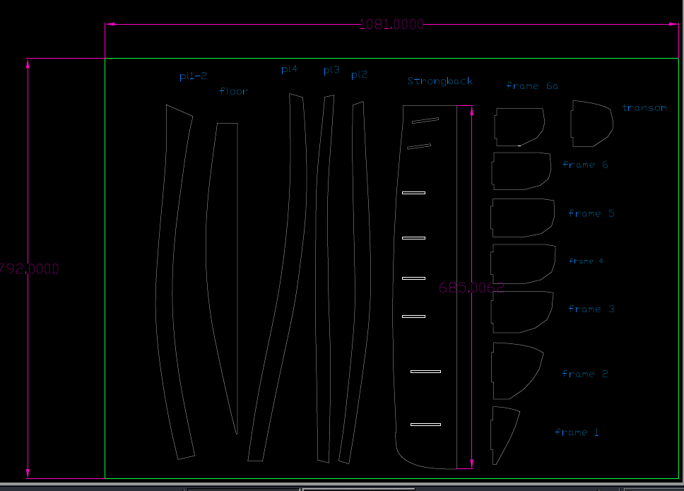
Next is moving further aft preparing frames 5, 6 6a and the transom.... not too much to do there, just pull out the CNC precut frames and add the doublers (seat supports, etc.) as detailed in the drawings.

P.S. : ... back to the centrercase: there is a slight error in the dimensions qoted in the drawings for the seat and deck supports to be glued each side of the box. I figured out the right ones using the corresponding heights in frames 3, 4, and 5

Tuesday 26 November 2013

Centerboard lifting mechanism

I decided to go a different route for the centerboard lifting mechanism. Basically it took us so long to finally have a small sailing boat with a potential fore "sunbathing platform" for my wife and I didn't want to spoil the dream by having taught ropes going across it.
In the original arrangement a 2 or 3 part block system is used to draw lines from the centerboard lifting point to the mast base.

In my version I will rather have pulley wheels fitted to the centerboard lifting point, to inside the forward log of the centerboard case assembly and on the deck at the base of the case itself.

Here's a sketch of the principle idea. The system of ropes is basically doubled up yielding a 4:1 purchase on the lifting effort. The lift line can be fed directly to the cockpit are or to a jammer on the side of the centerboard case.... no ropes fed to the mast step!


Here is how the implementation of the design look in a prototype set up. You can see the pulley wheels in slots routed in the case fore log. Also it should be quite clear how the system will eventually work.
For the moment it seems to be behaving extremely well and I am very pleased!!


Monday 11 November 2013

Centerboard shaping

As I mentioned in my previous post I was a little worried about how to shape correctly the centerboard stock.
Scouting a bit the boatbuilding forums I came across a very clever idea proposed by Ross Langford and appearing on duckworks magazine pages:
another approach to shaping foils

Great idea I thought right away, and I decided to follow its principle. Ross provides the complete solution including an excel sheet to design the router gig he proposes for the purpose.
For the fun of it I decided to apply the method but to redo the calculation, using 2D cartesian equations rather than trigonometry. I therefore wrote a MATLAB script that computes the foils NACA profile, its offset for the router cutter and finally outputs an AutoCAD script for printing purposes.
I am happy to provide the scripts to anyone interested ... they worked out pretty well!

Here's the model for my pathfinder's centerboard NACA profiler:

which is then used to build the router support:
 
And here we go, with the gig cut and assembled the router comes into (loud) play. The idea as that the router slides over the guide it cuts away the unwanted material from the centerboard stock, to obtained the required NACA profile.


The process is into two phases and mall portions of the centerboard are left unshaped to allow to turn the board around and shape its other face.   


Its great to see the NACA profile appear through the sawdust and the noise of the router.

I have no idea how I could have achieved a precise and constant profile throughout the board otherwise!

Wednesday 30 October 2013

The centerboard and its case

I am working on preparing and building the frames moving aft ... next step is the centerboard and its case.
The case doublers, seat and deck supports are now glued and before I can build up the case it is wise to build and give the right shape to the centerboard.
The board is glued from strips or lamells of both hard and softwood. Hardwood (mahogany) is mostly for the leading edge and the pivot area, while softwood (pine) is used elsewhere. While I was at it I also included a couple of hardwood strips in the middle of the lamination to ensure stiffness.

Once glued together, one realises how heavy and thick the stock is!
The profile of the board is so important as it affects the sailing performance of the boat. Not easy therefore to embark on this shaping task given what's at stake.
John Welsford (aka the boat designers) provides a template for the board cross shape. It goes from a 10mm radius circle at the leading edge, to maximum thickness (60mm) at 175mm and then tapers to 5mm thickness at the trailing edge.

Monday 21 October 2013

First go at some real boatbuilding...

This weekend  our Pathfinder build got into its actual operational phase. Enough fiddling with CAD software, printing templates on paper for checking, assembling scaled models, ... etc...
Hand over the epoxy and lets start putting together the parts we got just before the summer from the CNC cutting shop.
I decided to prepare each component of the boat frames from bow to transom. First on the list was therefore the stem profile, followed by frame 1, frame 2 etc..
At this stage I am glueing doublers and floor supports.

I could not resist and had a go at dry assembly the fore section of the boat. The notches I included in the cutting templates allow to place the frames precisley on the stem profile.
In these pictures is the progress over just a weekend. In the background hanging on the garage wall is the floor planks and their puzzle joints .


Sunday 18 August 2013

Holiday break

Holiday break...
no work ...
no time schedules...
no serious commitments


Just family fun and sailing in warm waters on our "Janas" sailing dinghy...

Great !!

Thursday 27 June 2013

Man.... this is a big boat

.... oh well, I know 17.2ft in water is not that much, but in a cramped garage it feels huge! Today I got the hull components home on my trusty ol' Fiesta. Couldn't resist and had a go at lining up the boat's floor, the stem profile, 2 widest frames and the transom just to have a gauge at the size of the boat.
Impressive! I think it'll end up being a little fiddly to work around it at stages in the garage, but once launched she'll be perfect for our intended use.

... consider that in this shot of the garage our little stornoway 12 "Janas" is missing while she's normally sitting on her trailer on the right hand side.


Tuesday 25 June 2013

Need shelves!

I've been fitting shelves all around the inner garage walls to store the CNC cut components for our Pathfinder. They are ready to collect from the company who provided the cutting service.

I will pick them up tomorrow in my Ford Fiesta!


Monday 10 June 2013

CNC cutting templates are ready

Yet another CAD step, this time fully 2D...
I exported the frame outlines from Inventor and the flat plank templates from Rhino right into AutoCAD that allows simple manipulation of 2D polylines.
I have then drawn the perimeter of the plywood sheet (2.5m x 1.22m) and started fiddling with the shape nesting.
At first I was not too efficient at nesting components but once I got the hang of it I managed to squeeze everything within 10 sheets of play, namely
- eight 9mm for the frames, the transom, all of the planking, the cb case, the rudder stock and blade and other bits and bobs
- two 12mm sheets for the floor and some doublers.

I also manage to save some surface for reusable leftovers.

Here's is how two of the nested sheets look like:


As you can see I elected to cut the frames in one piece only (unlike many other pathfinder builders). I also resorted to "puzzle joints" to join long pieces and align them properly. This applies for instance to the planking and the floor. My concern here was that given that the planking is cut already to the finished size, there is no margin for lining up errors.

The CAD drawings are now with a local company who has also received the Okoume marine ply sheets I bought.
They will cut the templates using their 3mx2m waterjet CNC cutter.... this will take approximately one day at a very  reasonable cost...


Monday 20 May 2013

Big day today!

No looking back ... I placed the order for 10 sheets of marine ply (eight 9mm thick and two 12 mm thick)...

There is no looking back from now on.

In the next post I will show how I got along nesting the CNC cutting shapes on the ply sheets.

Thursday 28 February 2013

The model looks fine!!

I received the waterjet CNC cut parts for the 1:8 scale model of the hull a few days ago. They include a strongback,  frames half shapes, the floor and the 4 planks.

My main concern is to verify whether the planks fit nicely to the frames and whether they overlap correctly all along their length. Plank overlap in the full scale boat is 25mm which will be down to about 3mm in my scaled model. I should therefore be able to verify the correctness of the 3D loft followed by the 2D unroll procedure I used to deduce the "flat" plank shapes using 3D CAD software.

While assembling the model I got the initial impression that things were not going too well, but that was down to the strongback being slightly warped. I then fitted it to a stiffer 12mm ply sheet and things fell sooooo nicely into place!


 The plank shapes are correct, the overlap is well maintained from bow to stern. Success!!

This is a pivotal moment in the project because it basically means that I can go ahead and have the hull components CNC cut out of 9mm and 12mm marine ply.

I now need to design the cutting layout for the frames, the stem profile,  floor, the 4 planks, cb case, seat sides and possibly other bits and bobs including rudder stock and frame doublers.

Lets see eventually how many sheets of ply I will require if I nest parts as tight  as possible...

Wednesday 23 January 2013

Trusting the software

Now as I mentioned in my previous posts I have modeled the hull shape in 3D CAD software to allow CNC cutting of all the required components for the build.

The question that was always buzzing in my head is whether the CAD model is correct. Did I draw the shape correctly according to the plan? Did the "unroll" feature to compute 2D templates for the planks do what it is expected to do? Would the plank shape "re-roll" themselves back into the correct 3D shapes once cut and placed onto the build frame??

Being unsure, and also perhaps for a bit of fun, I decided to have a scaled model CNC cut from thin plywood to the exact shapes that were obtained with the process described previously.

The idea is that if the scale model can be succesfully assembled  (i.e. the precut planks shape up and respect the overlap along their length correctly) that would give a strong indication on whether to move on to cut the real thing ... a whole bunch of costly marine ply sheets is at stake here.

Here's therefore the 1:8 scaled model pieces I asked a local company to CNC cut for me. They include  a strongback with notches where to fit frame half shapes. The floor and 4 planks were cut as well from the 2D templates computed in Rhino.


Saturday 19 January 2013

About CAD and CNC

I think the first milestone of the project has been achieved. I have redrawn the botas hull (frames, floor, stem and stern) in Autocad Inventor. I have then drawn the planks using the loft function. The plan was then to "unroll" the 3D surfaces resulting from the lofting procedure to obtain 2D flat shapes for subsequent CNC cutting (alongside the frames, floors, etc..).

Here's how the hull frames line up in Inventor:


 Unfortunately I found out that the "unroll" feature is not provided as standard in Autodesk Inventor and if I wanted to obtain 2D templates of the planks I had to look elsewhere.

I eventually found a viable solution after looking around on the web. I ended up redrawing the boats frames on another software for which a 60 day trial version is available free on the net. This software called Rhino 3D comes with an unroll feature for 3D surfaces. Having imported the frames (and the plank overlap offsets) from inventor I used Rhino's own loft function to draw the planks and then unroll them to Finally obtain the 2D flat templates of the planks I was after!

 Here's the hull modeled in Rhino. The plank overlaps of this beautiful clinker hull shape are visible. Rhino allows to click on a 3D surface and "unroll" to a flat template...


Great, now the whole boat is drawn in 2D . I will now use a third CAD program,  AutoCAD to compose the 2D shapes and arrange them within the typical size of ply sheets. The objectif is to efficiently nest the shapes to minimize costly marine ply waste.


Sunday 13 January 2013

Looking at the drawings

John's drawings are very detailed and easy to follow. The builders instruction booklet that came with them is also very useful.
It is a shame though that the plans do not include the drawings of the cabin as I expected .... or at least I thought from reading on the JW Builders Yahoo group. I contacted Fyne boat kits about this and they said that it is beyond them as they only supply the drawings provided to them by the designer.